
Why do you have to open the pneumatic crossfeed valves to de-ice the wings? Exactly what does the AC bus cross-tie switch do? And why do the engines only draw fuel from the center tank when all the fuel booster pumps are on? The key to understanding these and many other aspects of your aircraft is studying the schematic drawings for the various aircraft systems. That may sound a little bit dry, but to help you out I have included a Schematics section in the DC-9 Classic Flight Center that gives you live interactive schematic drawings.

From Wikipedia: “A schematic diagram represents the elements of a system using abstract, graphic symbols rather than realistic pictures. A schematic usually omits all details that are not relevant to the information the schematic is intended to convey, and may add unrealistic elements that aid comprehension.”

The Schematics section of the Flight Center has been designed to help you understand exactly what is going on with your aircraft and it’s systems at all times. Sometimes it can be difficult to fully understand exactly what happens when you flip a certain switch. The schematic drawings show you live exactly what is going on with the aircraft.

When you flip a switch on the electrical system, you’ll see which relay it is connected to and what happens when that relay closes or opens and how power distribution is affected as a result of that. You can also see how switches controlling various types of valves affect the fuel, hydraulic and pneumatic systems when operated. All the switches in the schematics are clickable. They operate just as they do in the cockpit and flipping a switch in the schematics will also flip the corresponding switch in the cockpit and the other way around.
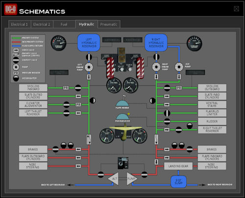
The Schematics section has five sub categories; Electrical 1 (AC), Electrical 2 (DC), Fuel, Hydraulic and Pneumatic.
